Open Systems Interconnection (OSI) Model
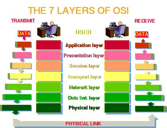
in this modal we learn about 7 layer:-
- APPLICATION LAYER
- PRESENTATION LAYER
- SESSION LAYER
- TRANSPORT LAYER
- NETWORK LAYER
- DATA LINK LAYER
- PHYSICAL LAYER
what is osi modal ?
The Open System Interconnection model is a seven-layer structure which outlines how communications should happen between computers with both the generalities (language and medium) and specifics of networks. This model was defined by the International Organization for Standardization and is officially referred as ISO OSI.
The OSI model is also called as Reference model because it relates to connecting systems that are open for communication with other systems. It ensures compatibility with different network technologies with the help of the descriptive network scheme and has become the widely accepted model for understanding network communication. Let’s get to know in detail about the OSI model.
1. The Physical Layer: This layer is responsible for transmitting and receiving the raw data through a physical medium. It provides the capability of data encoding that modifies the simple digital signal pattern to better accommodate the characteristics of the physical medium. This layer helps in finding out the transmission technique. Which determines whether the encoded bits will be transmitted by baseband or broadband signalling. This layer transmits bits as electrical or optical signals through physical transmission medium and find out which physical medium can be used and how much volt needs to be provided.
• Adapters that connect media to physical interfaces
• Connector design and pin assignments
• Hub, repeater, and patch panel specifications
• Wireless system components
• Parallel SCSI (Small Computer System Interface)
• Network Interface Card (NIC)
Components of the physical layer include:
• Cabling system components• Adapters that connect media to physical interfaces
• Connector design and pin assignments
• Hub, repeater, and patch panel specifications
• Wireless system components
• Parallel SCSI (Small Computer System Interface)
• Network Interface Card (NIC)
2. The Data Link Layer: This layer is responsible for error free transmission of data frames from one node to another over the physical layer.
• Offers a physical address so a device’s data can be sent on the network
• Works with a device’s networking software when sending and receiving messages
• Provides error-detection capability
• Ethernet and Token Ring switches
• Bridges
Layer 2 of the OSI model provides the following functions:
• Allows a device to access the network to send and receive messages• Offers a physical address so a device’s data can be sent on the network
• Works with a device’s networking software when sending and receiving messages
• Provides error-detection capability
Common networking components that function at layer 2 include:
• Network interface cards• Ethernet and Token Ring switches
• Bridges
3. The Network Layer: This layer is responsible for controlling the operation on the sub-net. While deciding which medium and path to be chosen by the data based on network conditions.
Layer 3, the network layer of the OSI model, provides an end-to-end logical addressing system so that a packet of data can be routed across several layer 2 networks (Ethernet, Token Ring, Frame Relay, etc.). Note that network layer addresses can also be referred to as logical addresses. Initially, software manufacturers, such as Novell, developed proprietary layer 3 addressing. However, the networking industry has evolved to the point that it requires a common layer 3 addressing system. The Internet Protocol (IP) addresses make networks easier to both set up and connect with one another. The Internet uses IP addressing to provide connectivity to millions of networks around the world. To make it easier to manage the network and control the flow of packets, many organizations separate their network layer addressing into smaller parts known as subnets. Routers use the network or subnet portion of the IP addressing to route traffic between different networks. Each router must be configured specifically for the networks or subnets that will be connected to its interfaces. Routers communicate with one another using routing protocols, such as Routing Information Protocol (RIP) and Open version of Shortest Path First (OSPF), to learn of other networks that are present and to calculate the best way to reach each network based on a variety of criteria (such as the path with the fewest routers). Routers and other networked systems make these routing decisions at the network layer. When passing packets between different networks, it may become necessary to adjust their outbound size to one that is compatible with the layer 2 protocol that is being used. The network layer accomplishes this via a process known as fragmentation. A router’s network layer is usually responsible for doing the fragmentation. All reassembly of fragmented packets happens at the network layer of the final destination system.
Two of the additional functions of the network layer are diagnostics and the reporting of logical variations in normal network operation. While the network layer diagnostics may be initiated by any networked system, the system discovering the variation reports it to the original sender of the packet that is found to be outside normal network operation. The variation reporting exception is content validation calculations. If the calculation done by the receiving system does not match the value sent by the originating system, the receiver discards the related packet with no report to the sender. Retransmission is left to a higher layer’s protocol.
4. The transport Layer: This layer is responsible for ensuring the error-free message delivery. It also takes care that no loss of data while transmitting and all the data sent should be in sequence. From this level the higher layer protocol is revealed. The type of service from the network layer decides the size and complexity of the transport protocol.
• Client-side entity identification
• Confirmation that the entire message arrived intact
• Segmentation of data for network transport
• Control of data flow to prevent memory overruns
• Establishment and maintenance of both ends of virtual circuits
• Transmission-error detection
• Realignment of segmented data in the correct order on the receiving side
• Multiplexing or sharing of multiple sessions over a single physical link
Some of the functions offered by the transport layer include:
• Application identification• Client-side entity identification
• Confirmation that the entire message arrived intact
• Segmentation of data for network transport
• Control of data flow to prevent memory overruns
• Establishment and maintenance of both ends of virtual circuits
• Transmission-error detection
• Realignment of segmented data in the correct order on the receiving side
• Multiplexing or sharing of multiple sessions over a single physical link
5. The Session Layer: This layer is responsible for establishing session between processes that are running on different stations.
Layer 5, the session layer, provides various services, including tracking the number of bytes that each end of the session has acknowledged receiving from the other end of the session. This session layer allows applications functioning on devices to establish, manage, and terminate a dialog through a network.
• Synchronization of data flow
• Creation of dialog units
• Connection parameter negotiations
• Partitioning of services into functional groups
• Acknowledgements of data received during a session
• Re-transmission of data if it is not received by a device
Layer 5, the session layer, provides various services, including tracking the number of bytes that each end of the session has acknowledged receiving from the other end of the session. This session layer allows applications functioning on devices to establish, manage, and terminate a dialog through a network.
Session layer functionality includes:
• Virtual connection between application entities• Synchronization of data flow
• Creation of dialog units
• Connection parameter negotiations
• Partitioning of services into functional groups
• Acknowledgements of data received during a session
• Re-transmission of data if it is not received by a device
6. The presentation Layer: As the name indicates this layer formats the data as to be presented to the application layer.
Layer 6, the presentation layer, is responsible for how an application formats the data to be sent out onto the network. The presentation layer basically allows an application to read (or understand) the message.
presentation layer functionality include:
• Encryption and decryption of a message for security
• Compression and expansion of a message so that it travels efficiently
• Graphics formatting
• Content translation
• System-specific translation
7. The Application Layer: This layer provides protocols to user window and applications processes. This also provides the application process to access network services and has many functions such as resource sharing, remote file access, printer access, and inter-process communication
Layer 7, the application layer, provides an interface for the end user operating a device connected to a network. This layer is what the user sees, in terms of loading an application (such as Web browser or e-mail); that is, this application layer is the data the user views while using these applications. application layer functionality include:
• Support for file transfers
• Ability to print on a network
• Electronic mail
• Electronic messaging
• Browsing the World Wide Web


Comments
Post a Comment
thank you for visiting :)